TA571-SIM - Input Simulator
- Input Simulator for 6 digital inputs 24 V DC
- For usage with AC500-eCo processor modules
Overview: Input Simulator TA571-SIM
Intended Purpose
The Input Simulator TA571-SIM is used for test and training purposes with AC500-eCo processor modules PM55x and PM56x. It can simulate 6 digital 24 V DC input signals to the digital inputs DI0 … DI5 of Onboard I/Os.
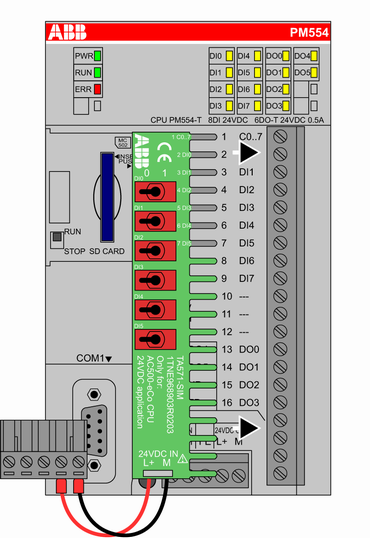
Electrical Diagram
The diagram below shows the electrical connection of the Input Simulator.
Mounting
To insert the Input Simulator follow the procedure shown below.
Make sure, that the power supply of the processor module is turned off.
Caution
:strong:Risk of damaging the PLC modules!
The PLC modules can be damaged by overvoltages and short circuits. Make sure, that all voltage sources (supply and process voltage) are switched off before you are beginning with operations at the system. Never connect any voltages > 24 V DC to clamp 4/5 of the terminal block of Input Simulator TA571-SIM.
Caution
:strong:Risk of damaging the Input Simulator or PLC modules!
The Input Simulator must only be used with AC500-eCo processor modules PM55x and PM56x. Never use the input simulator with other devices.
Note
The Input Simulator must only be used for test and training purposes. Never use it within productive plants.
Remove the Terminal Block for Power Supply from the processor module by a flat-blade screwdriver.
Make sure, that all clamps of the Onboard I/Os are totally open.
Use a flat-blade screwdriver to unplug the Terminal Block for Power Supply of the processor module.
Insert the Input simulator as shown in the picture.
Tighten all screws of the Onboard I/O clamps (max. torque 1.2 Nm).
Plug the Terminal Block for Power Supply of the TA571-SIM to the connector of the processor module.
Connect the processor module power supply wires (24 V DC or 100-240 V AC). See PM55x/PM56x Power Supply
Usage
With Input Simulator TA571-SIM, the digital 24 V DC inputs DI0 … DI5 of can be\ turned OFF and ON separately:
- If the lever of the switch is on the right side, the input is ON.
- If the lever of the switch is on the left side, the input is OFF.
Removal
To remove the Input Simulator follow the procedure shown below.
Make sure, that the power supply of the processor module is turned off.
Caution
:strong:Risk of damaging the PLC modules!
The PLC modules can be damaged by overvoltages and short circuits. Make sure, that all voltage sources (supply and process voltage) are switched off before you are beginning with operations at the system.
Disconnect the processor module power supply wires (24 V DC or 100-240 V AC) from the Terminal Block for Power Supply.
Unplug the Terminal Block for Power Supply with a flat-blade screwdriver of the power connector.
Loosen all screws of the Onboard I/Os.
Remove the Input Simulator by pulling it to the left side.
Technical Data
The System Data of AC500 and S500 System Data AC500 are valid here. Only additional details are therefore documented below.
| Process Supply Voltage | ||
| Connections | Terminal 4 (L+) for +24 V DC and terminal 5 (M) for 0 V DC | |
| Rated value | 24 V DC | |
| Max. ripple | 5 % | |
| Protection against reversed voltage | Yes | |
| Electrical isolation | Yes, per module | |
| Isolated Groups | 1 (6 channels per group) | |
| Weight | On request | |
| Mounting position | Horizontal or vertical | |
| Number of channels per module | 6 digital input channels (24 V DC) |
| Distribution of the channels into groups | 1 (6 channels per group) |
| Connections of channels DI0 to DI5 | Terminals 2 to 7 |
| Reference potential for the channels DI0 to DI5 | Terminal 1 (minus pole of the process supply voltage, signal name C0…7) |
| Input current per active channel (At input voltage +24 V DC. The current is given through the used processor module.) | Typ. 5 mA |
| Inrush current (Per active channel. The current is given through the used processor module.) | Typ. 5 mA |
Ordering Data
| Ordering No. | Scope of Delivery |
|---|---|
| 1TNE 968 903 R0203 | TA571-SIM, Input Simulator for PM55x and PM56x |