| Digital inputs |
4 inputs (2 inputs per axis)
- Input 0, Input 2: Enable input used for limit switches and enable signal (3 signals in 1 chain)
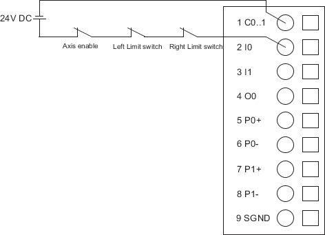
- Input 1, Input 3: Stop/Registration input used as interrupt input
- Stop: emergency stop and give the actual position information, the deceleration value can be set via the Function Block which is provided by the library.
- Registration: give the actual position information, number can be viewed via the Function Block which is provided by the library, the registration input can be used for homing.
|
| PTO outputs |
PTO output mode can be configured by parameters.
- 2-axis control in 1 module
- PTO output type: RS-422 differential output
- PTO frequency: 0..250 kHz
- Configurable PTO output mode: Pulse + Direction / CW + CCW
- CW/CCW (clockwise/counterclockwise): pulse string is set out on 1 of the 2 differential channels according to motor rotation direction. The output channel is defined by a Function Block.
Pulse+ / Pulse- (CW/CCW)
PTO Output 0 (CW)

PTO Output1(CCW)

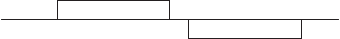
- Pulse/direction: 1 differential channel for pulse string and 1 differential channel to set direction of movement
Pulse + Direction (Pulse / Direction)
PTO Output 0 (Pulse)

PTO Output 1 (Direction)
|
| Power supply for encoders |
- Input voltage range: 18..31.2 V DC
- Reverse polarity protection: withstand 10 s
- Surge voltage: 35 V for 0.5 s
- Allowed interruptions of power supply :interruption < 10 ms, time between 2 interruptions > 1 s
- Isolation: 1.2/50 µs Impulse peak 500 V
|
| LED displays |
- 1 green LED for PWR (I/O Bus power)
- 1 red LED for ERR
- 1 yellow indicator for each digital input/output channel
- 1 yellow LED indicator for each pulse output channel
|