Programming in CFC
Connecting Elements
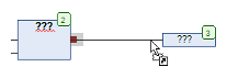
Drag a Box element and an Output element in the editor.
⇒
Click the output of the Box element.
- ⇒
The output is marked by a red square.
Drag a connecting line from the output of the Box element to the input of the Output element.
- ⇒
The cursor symbol changes when it reaches the input pin.
Release the mouse button.
- ⇒
CODESYS connects the two elements together by a connecting line.
Alternatively you can also select the two pins with the Ctrl key pressed and select the Connect Selected Pins command.
See also
Creating of connection marks
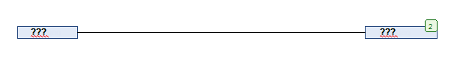
Requirement: A CFC POU has connected elements.
Select a connecting line between two elements.
- ⇒
The connecting line is marked; the input or the output of each element is marked with a red square
 .
.
Select the command .
- ⇒
The connection is disconnected and replaced by a connection mark - source and a connection mark - sink. The names of the marks are automatically generated.
Click in the connection mark - source.
- ⇒
The name can be edited.
Change the names of the source and the target to the same names.
Example 1
Example 2
Example 3
See also
Resolving collisions - Adapting connecting lines by control points
The following example shows you how to use the Route All Connections command, as well as how to use control points.
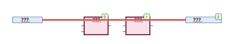
Position the Input and Output elements in accordance with the following example and connect the elements
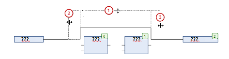
Position two Box elements on the line.
- ⇒
The connecting line and the function blocks are drawn in red due to the collision.
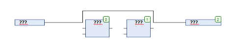
Execute the command .
- ⇒
The collision is dissolved
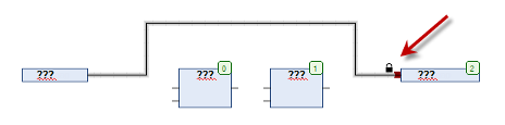
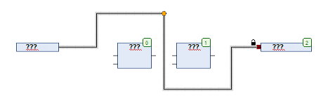
Change the connecting lines in 3 steps in accordance with the following example
- ⇒
The connecting line was manually changed, so that CODESYS disables it for the automatic routing. This is indicated by a lock at the end of the connection.
Position a control point on the connecting line.
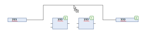
Change the connection in accordance with the following example
- ⇒
Through the control point you can change the connecting line individually. You can set as many control points as you wish.
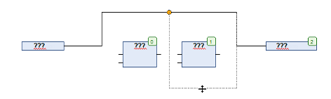
Remove the control point using the context command . Disconnect the connection with the command or by clicking on the lock symbol.
Select the connecting line and select the command.
- ⇒
The connecting line will be drawn automatically as illustrated in step 3.
Attention
Autorouting does not affect grouped connections.
See also
Changing the execution order
The order in which the elements of a CFC network in online mode are successively executed is indicated by the element numbers in the top right corner of each element. Execution starts with the element with the lowest number, “0”.
When pasting in an element, CODESYS automatically assigns the number in the topological order (from left to right and from top to bottom). If the order has already been changed, the new element receives the number of its topological successor and all higher numbers are increased by one.
The number of an element remains constant when it is moved.
Please bear in mind that the order has an effect on the result and has to be changed in certain cases.
Select the element whose order of execution you wish to change
- ⇒
The element is displayed with a red border
Select the command
- ⇒
Select the command
See also
- Command ‘Send to Front’
- Command ‘Send to Back’
- Command ‘Move Up’
- Command ‘Move Down’
- Command ‘Order by Data Flow’
- Command ‘Order by Topology’
See also